Wednesday, January 22, 2014

Reusing some old microcontrollers Arduino style

The other day I was cleaning up my electronics boxes and I happened on 2 older Atmega32 40 pin controllers I got a long time ago, when first starting my foray into MCUs. I remember those times when I was trying to figure out how to program a controller, when no Arduino was around and everything was done directly in C at pin level, same as I still do now for MSP430; with lots of friends and forum help, I was able to blink an LED even drive an H-Bridge. Cool and also frustrating times! An idea struck me: if people are able to create Arduino like IDEs for all kinds of controllers (see Energia for MSP430 and LaunchPad) maybe it would be possible to program these MCUs the same way: after all, they are Atmel controllers so it shouldn't be that difficult. It all has to start with burning the bootloaded, since this is what makes the Arduino what it is today. It turns out some people figured out how to do this, not very easy but not very complicated either. The post I found most helfpul is here. Thousand thanks to hexskrew for figuring this out!

First thing to do was install Arduino-0022 (I already have 1.0.5 installed but the arduino-extras was written for pre-1.0 versions, didn’t want to go through the pain of updating the code and mess it up for sure) and replace the arduino folder with the content of arduino-extras.zip. Also, in Preferences, I unckecked “Check for updates on startup” because I want to keep this Arduino version as it is - newer versions will apply to my other Arduino-1.0.5 install.

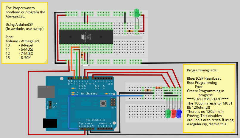
Most important step is wiring the Atmega32 to the Arduino: I have an ISP programmer somewhere but using an Arduino instead seemed to be easier for someone like me. The schematic is shown here and is great!I wired everything as in the image but since I didn't have a 120 ohm resistor, I decided to use a close one instead, 150 ohm. It says clearly in the image that the resistor MUST be 120 ohm but my limited experience said: if 120 ohm can do the job, why not a 150 ohm! Big mistake that cost me quite some time! (Now I know I should listen to my betters and not assume anything, especially since I am just a noob in electronics.) Running the first command in the document:

avrdude -p m32 -c arduino -P /dev/ttyUSB0 -b 19200

I got instead of the expected response:

avrdude: Device signature = 0x1e9502

this:

avrdude: Device signature = 0x1e9406
avrdude: Expected signature for ATMEGA644P is 1E 96 0A
Double check chip, or use -F to override this check.


I googled around and found the same exact message in this post which in turn links to this doc in Arduino playground where it is explained with details that the resistor must indeed be 120 ohm! I dug into my box of resistors in the end found a few that connected together yielded the desired 120 ohm. I reran the previous command again and this time I got the expected reply. Awesome!

Note: there is a difference between the original schematic I followed and the last article I mentioned: in the original one, the 120 ohm resistor is between RESET and GND; in this article is between RESET and 5V. I assume they both worked but I decided to go with RESET to 5V.

The commands are listed and detailed in the post I mentioned above, in a nutshell what I did to burn the bootloader was:
  1. Check everything is ok
  2. Set the chip to be unlocked, and use the internal 8mhz oscillator
  3. Unlock to bootloader
  4. Flash the arduino bootloader
  5. Lock the bootloader.
After this was done, I got the example sketch and tried to compile. I had several errors some that may have been Linux Mint specific (maybe because I already have newer avr libraries installed for Arduino-1.0.5) but this and this posts helped me fix them so in the end the sketch compiled successfully. I uploaded it to the Atmega32 the way it is described in the post - I still need to figure out how to upload it directly without copying it manually from /tmp to /bin. It was getting late when I finished this so I didn't get to test it - I assume I will have to disconnect the SPI communication with the Arduino first. I'll try soon and post back here.

Again, big thanks to hexskrew for figuring this out!

Tuesday, January 21, 2014

Amazing graphs

This post is only indirectly related to Raspberry Pi, Arduino and cloud data because I found out about this great website, plotly by reading this post on Quora: What is a good first project with a raspberry pi?. And while the website itself and the Arduino code look great, I was amazed by the blog content: each graph is not only telling a story but it is really beautiful as well, like this one.

Check them out: http://blog.plot.ly/

Sunday, January 12, 2014

My first smartmaker tiny projects

After more than one year, some of the smartmaker boards made it so I started to play around with them a little bit. First, I have to say that they are pretty cool: it is a lot easier to connect the boards than to put together circuits on breadboard. The docs are still lacking, there are still problems with some boards and I am a bit worried that the connectors may not be quite so resilient in time (for all of these issues and more, visit the smartmaker forums) but overall I like the idea.

First things I tried were pretty simple things (all of these are public projects in my codebender account): changing colors on the RGB led, make 5 leds blinks, read the values of 5 analog buttons and drive 5 leds using 5 analog buttons - the last one was a real hit with my son, he loved pushing one or more buttons to see the corresponding leds turn on.

As a side note, the RGB led board received from smartmaker was not in my original list of boards ordered, as someone mentioned in the forums it seems this was a small gift from smartmaker, so thanks a lot, Dimitri@smartmaker.

The projects I mentioned are nothing special but one thing about them is really cool: think about putting together a circuit with 5 analog buttons and 5 leds; in addition to the buttons and leds, one would need resistors, 10 in this case, wires between the arduino and the breadboard and a lot of patience. It was a breeze to snap a smartcore into an extension board, and the buttons and led boards into another extension board, connected in turn to the first board; seconds really. This is the smartmaker idea that I loved from the start and that I hope will be successful.

A quick photo of the last project I mention is below:

For more info, there are some really nice tutorials posted on the forums by Josephur, specifically here.